Available machine vision cameras are defined using a data frame, which must contain 11 fields, whose meanings are described in the following list. The names of the fields need not be the ones used in the list, but their order and data type (s = string, i = integer and f = float) must be the same as in this list.
The data connection string specifies, how the camera is connected to the computer and which connection address is used. The string must start with a connection type specification. This should be one of the following:
The control connection and control settings should only be specified if the camera settings can be altered using a serial port. For example, rs:com1 specifies that the RS-232 serial port number 1 is used for communication and 9600_8n1 specifies that the communication settings are 9600 bits/s, 8 data bits, no parity and 1 stop bit. Communication speed can be any baud rate, which is supported by the camera and the PC, number of bits should be between 5 and 8 (inclusive), parity can also be even, odd or mark, and there can be 1 or 2 stop bits.
The separator character is used both while parsing the settings acquired from the camera and while sending (possibly) altered settings to the camera (it should exist between all setting - value pairs). respons is the string, which is received from the camera, if a sent command is accepted. All other responses are interpreted to denote that an error occurred while using the control connection. Control connection currently supports only cameras manufactured by JAI Inc.
width and height specify the resolution of the camera in pixels.
The cameras can be either grayscale or color.
The number of color channels should be larger than 1 only for such cameras,
which give the image out as for example three 8 bit red, green and blue
channels.
For grayscale cameras and Bayer filtered color cameras it should be 1.
The Bayer coded color images can be later converted either to grayscale or
to color images in the computer.
The physical CCD cell dimensions must be given in millimeters.
They are needed for the camera calibration methods.
The dimensions are approximately
![]() millimeters for
1.33:1 aspect ratio 1/2 inch CCD cells and
millimeters for
1.33:1 aspect ratio 1/2 inch CCD cells and
![]() millimeters for 2/3 inch cells with the same aspect ratio.
millimeters for 2/3 inch cells with the same aspect ratio.
Since each camera is represented by one line in the data frame, they can be referred to by the (zero-based) row number. This implicitly defined (zero-based) number is the camera ID, which should be used in the image acquisition and camera control commands.
An example of a camera definition frame:
datacon                    ctrlcon  ctrlset   separtr  respons
imaq:img0.0                rs:com1  9600_8n1  =        COMPLETE
imaq:img0.1                none     na        na       na
socket:192.168.1.120:2002  none     na        =        OK
foculus:0                  none     na        na       na

width  height  colorch  depth  ccdw   ccdh
1380   1035    1        8      6.417  4.81275
768    576     1        8      6.417  4.81275
768    576     1        8      6.417  4.81275
1280   960     1        8      6.417  4.81275
In the frame none means that such connection does not exist and na means that the value of that field is not applicable to that camera type. The settings of ethernet (and IEEE1394) cameras can be adjusted even though no (serial-port-based) control connections to them are available.
| grab | Show live image from a machine vision camera |
| -d <cameras> | camera definition frame |
| [-id <choice>] | ID number of the camera to be used |
| [-panel <hpanel>] | frame defining the user interface panel to be used for display |
| [-w <width>] | width of the window to be created if panel is not used |
| [-h <height>] | height of the window to be created if panel is not used |
| [-histo] | calculate and display the grayscale histogram of the image |
| [-focus] | calculate and display the focus value of the image |
| [-opcode <codeval>] | code value to be sent to an Ethernet camera server |
| stopgrab | Stop the showing of live image from a machine vision camera |
| -window <window> | window id number of the user interface panel to be used |
Live image from machine vision cameras can be shown both in a separate window or within the NDAshell application GUI panel, and it is always run as a separate thread in the background. In order to use the ``embedded to GUI'' approach, a handle panel (# COMPONENT=THandlePanel; NAME=<pan_name>; ...) needs to be defined within the NDAshell GUI definition, and the panel needs to be specified to grab using (-panel /ui/<pan_name>). If a panel is not specified to grab, it creates a new window, whose size can be defined using <width> and <height>. The controls in this new window can be used for selecting the camera, and for starting and stopping the live image display.
If the ID number of the camera is not specified to grab, the first camera in the camera definition frame is used. If the width or height of the camera image is greater than 1000 pixels, the image is scaled down to half of original (in both directions) before display. Grabbed image from a Bayer camera is displayed in grayscale without pixel interpolation.
-histo and -focus toggle the calculation and display of histogram and focus value on. The image obtained from Vision Components Ethernet cameras may be a raw image or a processed or analyzed one depending on the server application used in the camera. <codeval> can be used for defining several services into one server application, since this code is sent inside the image acquisition request into the camera and since the camera can process the image according to this code before sending it to the NDA application.
If a GUI handle panel is used, live image display can be stopped using stopgrab by defining the window id of the panel (${/ui/<pan_name>.handle}) to switch -window. If live image display is directed into a separate window, the controls in that window can be used to end grab (or the window can simply be closed).
Example: Live image display is directed into a defined
handle panel. The machine vision cameras are stored in the
frame cameras and we wish to use the first camera. The
gray value histogram and focus value of the image are also
shown. The image display is later stopped with stopgrab.
...
# COMPONENT=THandlePanel; PARENT=Grab; NAME=GrabHPanel; ...
...
NDA> grab -d cameras -id 0 -panel /ui/GrabHPanel -histo -focus
...
NDA> stopgrab -window ${/ui/GrabHPanel.handle}
| imsnap | Snap one image from a machine vision camera |
| -d <cameras> | camera definition frame |
| -id <choice> | ID number of the camera to be used |
| -iout <name> | name for the acquired image |
| imacqseq | Acquire a sequence of images from a machine vision camera |
| -d <cameras> | camera definition frame |
| -id <choice> | ID number of the camera to be used |
| -iout <prefix> | name prefix for the acquired image(s) |
| [-count <count>] | number of (consecutive) images to acquire |
These two operations acquire and save images from machine vision cameras. imsnap acquires only one image and returns. imacqseq acquires several images (consecutive, if possible) and saves them using a common name prefix. The names of the consecutive images become <prefix><nnn>, where <nnn> denotes the three-digit zero-based image number within the sequence (leading zeros are inserted, if needed). <prefix> may not contain '%' characters, and the maximum number of images in a sequence has been limited to 256. The type of the saved images is the one used in the revised image processing commands (struct im), but subtype depends on the used camera.
Example: The following commands acquire a single image
and a sequence of images:
NDA> imsnap -d cameras -id 0 -iout img
NDA> imacqseq -d cameras -id 1 -iout imseq -count 3
NDA> ls -l
...
struct im     1380x1035   8i   1403.0kB /img
struct im      768x576    8i    436.6kB /imseq000
struct im      768x576    8i    436.6kB /imseq001
struct im      768x576    8i    436.6kB /imseq002
| camread | Read the settings from a machine vision camera |
| -d <cameras> | camera definition frame |
| -id <choice> | ID number of the camera to be used |
| -fout <setts> | name for the field where settings are to be stored |
| camalter | Change camera settings |
| -f <original> | original settings to be altered |
| -fout <output> | name for modified settings |
| [-vals <name>=<value> ...;] | name and value pairs |
| camwrite | Write (modified) settings to a machine vision camera |
| -d <cameras> | camera definition frame |
| -id <choice> | ID number of the camera to be used |
| -f <setfld> | name of field containing settings |
These three commands can only be used with such machine vision cameras, which support a serial control connection. Ethernet cameras can be queried and adjusted using the commands camrecv and camsend (introduced below), if the server application in the camera supports it.
camread reads the settings from a machine vision camera, parses the result by separating parameter names from parameter values using the separtr field value of the camera frame, and writes the result into a field in format <name>=<value>. camalter can be used to alter a subset of parameters by giving new values to chosen named parameters. Settings can be written into the camera using camwrite, which reads and parses the specified settings field and then communicates them into the chosen camera.
Example: The following commands read, alter and write the
settings from/to a JAI CV-A1 camera. The shutter time is changed
into 1/60 s (value of SH is set to 2) in the example.
NDA> camread -d cameras -id 0 -fout setts
NDA> camalter -f setts -fout s_out -vals SH=2;
NDA> camwrite -d cameras -id 0 -f s_out
| camsend | Send data to an ethernet machine vision camera |
| -dcam <cameras> | camera definition frame |
| -id <choice> | ID number of the camera to be used |
| -dd <data> | name of frame containing settings |
| [-opcode <codeval>] | operation code for the request |
| camrecv | Receive data from an ethernet machine vision camera |
| -dcam <cameras> | camera definition frame |
| -id <choice> | ID number of the camera to be used |
| -fout <setts> | name for the field where settings are to be stored |
| [-opcode <codeval>] | operation code for the request |
| [-x <left>] | ROI specification, x-coordinate of left edge |
| [-y <top>] | ROI specification, y-coordinate of top edge |
| [-w <width>] | ROI specification, width of subimage |
| [-h <height>] | ROI specification, height of subimage |
These commands can be used for sending and receiving arbitrary data from/to ethernet cameras. The supported operations are determined by the camera server application. Examples of operations include altering of camera settings, sending lens calibration data from the computer to the camera, or receiving image based measurement results from the camera (camera takes an image, detects and measures the size of the object in the image, converts the dimensions given in pixels into millimeters using lens calibration data, and sends the results back to the computer).
Example: The following commands first take a calibration
image using the chosen Vision Components ethernet camera,
calculate calibration data based on that image, send the
calibration model into the camera, and then request the
camera to measure an object. As the result, the dimensions
(in millimeters) are stored into the field dims_mm at
the computer.
NDA> imsnap -d cameras -id 2 -iout calib
NDA> CreateCalibModel calib cal_model
NDA> camsend -dcam cameras -id 2 -dd cal_model -opcode 16
...
NDA> camrecv -dcam cameras -id 2 -w 768 -h 576 -fout dims_mm \
     -opcode 32
| stopsrv | Stop the ethernet server from a machine vision camera |
| -d <cameras> | camera definition frame |
| -id <choice> | ID number of the camera to be used |
This command can be used to stop the ethernet server program from the chosen Vision Components camera.
Example: The following command stops the ethernet server
in the ethernet camera, whose ID is 2.
NDA> stopsrv -d cameras -id 2
The following commands can be used for acquiring data from the states of electrical signals. Data acquisition is based on National Instruments NI-DAQmx programming library and uses National Instruments hardware to take samples from the specified analog and digital signals. Digital signal based triggers can be used for starting and ending the acquisition, and a predefined maximum amount of acquisition time has to be specified in milliseconds. The signals are sampled using a predefined rate (samples / second) and the number of cycles to record can be either predefined or inifinite (until acquisition is explicitly stopped).
The data acquisition can be run either as the only NDA task or in the background inside a separate program thread. If acquisition is put into separate thread, other tasks can be done simultaneously. Data acquisition is able to display graphs of the collected cycles inside an NDAshell GUI.
The source signals need to be defined using data frames in the following format. Analog signals are defined using the following fields:
The acquisition can store the analog signals either as voltage levels,
![]() , or convert the acquired voltages into the magnitudes of the physical
source,
, or convert the acquired voltages into the magnitudes of the physical
source, ![]() .
This conversion is done using the formula:
.
This conversion is done using the formula:
The properties of a data acquisition task are stored in a frame, which contains most of the information specified above and the starting date and time of the acquisition. In addition, the starting date & time and number of samples of each cycle is stored in another frame, and the basic statistical properties (minimums, averages and maximums) of each analog signal are stored in a third frame.
The actual acquired data is stored in an NFRAME, which contains one data frame for each acquisition cycle. The data frames, which contain the data of one cycle is stored using names analog<n> and digital<n>, where <n> is the (zero-based) number of the signal. Analog signals are stored as floating point fields and digital signals as integer fields (containing only values 0 or 1). In addition, the output data frame contains a field called time, which contains the relative acquisition time of each sample (starting from 0.0 seconds).
An example of all stored data is shown in the figure below.
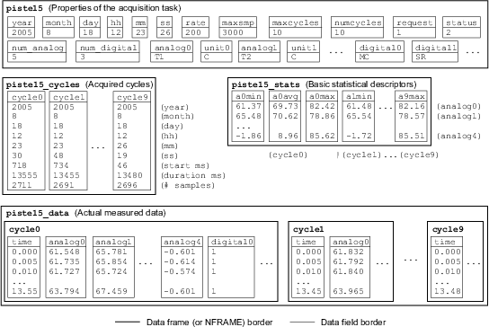
The acquisition task data contains at least two fields, which are useful: numcycles contains the number of cycles acquires so far, and status contains the current status of the acquisition: 0 - Waiting for trigger, 1 - Acquiring data, 2 - Successfully finished, 3 - Interrupted by user, 4 - Acquisition failed, or any negative value - NDA error number.
| setupdaq | Start a data acquisition task |
| -analog <afrm> | analog signal definition frame |
| -digital <dfrm> | digital signal definition frame |
| -dout <dataout> | frame name for acquisition data |
| -cycles <cycles> | frame name for cycle data |
| -curves <curves> | frame name for actual curve data |
| -stats <cstats> | frame name for curve statistics |
| -rate <srate> | sampling rate (samples/s) |
| -time <millisec> | maximum acquisition time in milliseconds |
| [-runs <ncycles>] | maximum number of acquisition cycles (default infinite) |
| [-strig <start>] | start trigger definition |
| [-etrig <end>] | end trigger definition |
| [-panel <panel>] | GUI handle panel definition frame (used for graphs) |
| [-graph <grdef>] | graph definition string |
| [-start] | start acquisition immediately (or after start trigger) |
| [-thread] | put acquisition in separate thread |
| [-volts] | store data as volts instead of physical quantities |
This command can be used to start data acquisition from electrical signals. <afrm> and <dfrm> specify the signals to be acquired, <srate> defines the data acquisition rate, <millisec> limits the maximum acquisition time, and <ncycles> can be used to define the maximum number of acquisition cycles.
Basic acquisition information is stored in <dataout> (including the date and time information), cycle information in <cycles>, statistics about the analog signals for each cycle in <cstats>, and the actual curve data in NFRAME <curves>. Inside <cycles> and <curves> the cycles are named cycle<n>, where <n> is the (zero-based) number of the cycle.
If -start is not specified, the acquisition will wait until the request field of <dataout> is changed from 0 to a different value (a negative value will end the acquisition and a positive value will start it). The acquisition will, of course, wait for the start trigger, if such has been defined. The acquisition of each cycle will continue until either the end trigger condition is encountered or until the maximum acquisition time has passed.
Triggers are defined using digital signal names and a postfix, which indicates the direction of the signal change (:01 if the signal should change from 0 to 1 and :10 if the opposite change is expected). Please note that first the signal must be in the initial state and then change to the target state while the acquisition is active. If the signal is initially in the target state, the acquisition will wait.
The acquired data can be visualized by defining a handle panel for the graph using <panel>, and by defining the contents of the visualization using <grdef>. The format of <grdef> is {<gr1>,<gr2>|all}[,{<gr3>,<gr4>|all}], where each 'gr<i>' is either min:, avg: or max: followed by an analog signal name or 'none'. 'all' causes the visualization of all acquired signals and it fills either the left or right side of the visualization. <gr1> defines the graph for the top left corner, <gr2> bottom left, <gr3> top right and <gr4> bottom right. If the statistical descriptors of analog signals are requested, those graphs will contain lines, which represent all collected cycles of this acquisition task.
Example: The following command starts the data acquisition
of analog and digital signals (defined by the data frames
analog and digital), it uses MC (mold closed)
signal as trigger and will collect data at rate 500 S/s
for up to 20 seconds of 10 cycles. The data is acquired
in separate thread, and the signals of the current cycle
and the average of T1 and maximum of P1 of all cycles
are visualized in a handle panel defined by /ui/DaqHPanel.
NDA> getdata analog -tab
device  channel  umin   umax   name  unit  min  max
0       0        2.0    10.0   T1    C     0.0  200.0
0       1        2.0    10.0   T2    C     0.0  200.0
0       2        0.0    10.0   P1    bar   0.0  2000.0
0       4        0.0    10.0   P2    bar   0.0  844.5
0       5        0.074  6.043  pHyd  bar   0.0  250.0
NDA> getdata digital -tab
device  port  line  name
0       0     0     MC
0       0     1     SR
0       0     2     IF
NDA> setupdaq -analog analog -digital digital -strig MC:01 \
     -etrig MC:10 -dout daqdata -cycles daqcyc -curves daqcrv \
     -stats daqstat -panel /ui/DaqHPanel -graph all,avg:T1,max:P1 \
     -rate 500 -time 20000 -runs 10 -start -thread
| stopdaq | Stop a data acquisition task |
| -d <daqdata> | frame containing acquisition data |
| -fout <statout> | name for status field |
| [-timeout <seconds>] | maximum time to wait (default is 60 s) |
This command can be used to stop the data acquisition from electrical signals. The acquisition is stopped as soon as the current cycle has been finished. Timeout can be specified using <seconds> (default is 60 seconds) and status is returned in <statout> (0 - could not stop, timeout reached, 1 - Stopped successfully, 2 - Acquistition was already stopped).
Example: The following command will stop data acquisition
(if it is still active) and return status in dsstat.
NDA> stopdaq -d daqdata -fout dsstat -timeout 60
The Engel Monitoring System is a comprehensive control and data collection application for injection molding machines (IMMs) manufatured by Engel AG. One small part of it, Basic Module / File Interface, is an implementation of the EUROMAP 63 standard, which can be used for file based communication between one PC computer and several IMMs.
This file based communication interface makes it possible to collect data from the production cycles and to change the controllable parameters of the IMM. When the PC writes a file to a predefined communication directory, the EMS system reads the file, and if the syntax of the file is correct, further passes it as a task to the IMM. The collected data is written back to the PC as soon as each production cycle has completed.
In order to be able to use this NDA communication ability, the EMS system has to have been installed in the computer and it has to be configured properly. Then, the EMS system must be started prior to initiating the NDA command emssetup, because at that point, NDA will check that the communication with EMS is functioning properly. EMS can be used for communicating with several IMMs at the same time. However, current NDA implementation is only capable of communicating with one IMM at a time.
For NDA the IMMs are defined using a frame containing:
emsdir  idnum
C:/EMS  65535
which thus defines the EMS installation directory (which contains MACHINE.INI and the directories used for communication) and the machine ID numbers (one line for each IMM). Please note, that in the EMS directory definition, slashes should be used instead of backslashes.
Almost all communication requests need a set of EUROMAP machine parameters. These parameters are then used for defining the parameters to be read or set. The NDA implementation requires that the parameters need to be given as a frame containing readable names, original parameter names and parameter types (1 = integer, 2 = float, 3 = integer). The original parameter names can be obtained using the GETID EUROMAP command. Here is an example of NDA's EMS parameter list (initial letter S = parameter for set, M = measured parameter):
name      parameter      type
SHPTime   @08101         2     # Holding press time
SCTime    @08000         2     # Cooling time
SHPress   <ems_phold     1     # Holding pressure
hold1     @06101         1     #  hold press zone 1
hold2     @06102         1     #                  2
hold3     @06103         1     #                  3
...
hold10    @06110         1     #  hold press zone 10
SMelt     <ems_melt      1     # Melt temperature
melt1     @14000         2     #  melt temp zone 1
melt2     @14001         2
melt3     @14002         2
melt4     @14003         2     #  melt temp zone 4
SMold     <ems_mold      1     # Mold temperature
mold1     @23112         1     #  mold side 1
mold2     @23113         1     #  mold side 2

MMelt1    @15200         2     # Measured melt temp 1
MMelt2    @15201         2
MMelt3    @15202         2
MMelt4    @15203         2     #  melt temp 4
MMold1    @15242         2     # Outcoming water
MMold2    @15243         2     #  temp from mold
MCycTime  ActTimCyc      2     # Cycle time
MITime    ActTimFill[1]  2     # Injection time
MPTime    ActTimPlst[1]  2     # Plasticizing time
MISpeed   @02184         2     # Injection speed
MIPress   @06514         2     # Injection pressure
MCushion  @02511         2     # Cushion size
Year      @01899         1     # Date
Month     @01900         1
Day       @01902         1
WDay      @01901         1     # Day of the week
Hh        @01903         1     # Time
Mm        @01904         1
This example specifies five controllable parameters: holding pressure time, cooling time, holding pressure value, melt temperature and mold temperature, of which the latter three are specified using profiles:
ems_phold:
  value  hold1  hold2  hold3  ...  hold10
  100    100    100    100         100

ems_melt:
  value  melt1  melt2  melt3  melt4
  230    230    225    220    215

ems_mold:
  value  mold1  mold2
  70     70     70
These profiles make it possible to use those three parameters in a DoE, where each modifiable parameter has to be a single entity. For example, when the parameter SHPress is given a new value, say 85, the system uses the profile, which is specified in the parameter field after the less-than sign. NDA automatically locates the closest value to 85 from the first (value) field of the profile and then uses the names of the other profile fields, to locate the actual parameters to be set: from @06101 to @06110, and makes the needed EUROMAP SET commands, which change all these parameters to the value 85 (because the profile says that all those fields should be given the same value as SHPress). In the case of SMelt, a value of 250 would result in settings, where the value of melt1 would be equal (250), but melt4 would be given a 15 degrees smaller value (i.e. 235), for example.
The use of EMS has been divided into three NDA commands: 1) emssetup - initialize and test functionality, 2) emsmonitor - start reports or collect data, 3) emsset - change IMM controllable parameters. There can be only two reports active at a time, one that collects data from all cycles inifinitely (until that reporting task is explicitly finished), and another, with which a predefined number of cycles can be collected.
| emssetup | Initialize EMS communication and test functionality |
| -d <data> | data frame containing the EMS directories and IMM IDs |
| -fout <commdir> | name for the field into which the communication directory is stored |
| [-id <imm-num>] | number of the IMM to communicate with (default 0) |
| [-stat <statout>] | name for optional status output |
| [-timeout <seconds>] | amount of time to wait for EMS response (default 10, 0 = inifinite) |
This command initializes EMS communication by locating the MACHINE.INI file from EMS installation directory, by reading the communication directory for the chosen IMM from that file, and by writing a CONNECT EUROMAP command into that directory. If a non-erratic response is received from EMS before the specified timeout is reached, the used communication directory is stored into <commdir>. This directory can later be used with other EMS commands.
If the CONNECT command is not successful (either no response or an error is received), emssetup will either write a response to the status field (<statout> if it is specified) or return an error. Possible responses include: 0 - success, 1 - error in EMS response, 2 - timeout, 3 - CONNECT failed, 4 - Error in MACHINE.INI, and 5 - error in <data> or MACHINE.INI not found.
Example:
...
NDA> getdata emsdata -tab
emsdir  idnum
C:/EMS  65535
NDA> emssetup -d emsdata -fout emsdir
NDA> getdata emsdir -tab
C:/EMS/MACHINES/65535/E63_JOBS
| emsmonitor | Use EMS to collect data using reports |
| -dir <commdir> | field containing the EMS communication directory |
| {-par <params> | EMS parameter definition frame |
| -f <rep-list> | | list of parameters to report |
| -dout <dataout>} | frame name for collected data |
| [-all] | report all cycles inifinitely (or until stopped) |
| [-nowait] | do not wait any (even non-inifinite) report |
| [-runs <ncycles>] | number of cycles to report (default 1) |
| [-stat <statout>] | name for optional status output |
| [-timeout <seconds>] | amount of time to wait for EMS response (default 10, 0 = infinite) |
When starting a report, one has to first call emsmonitor with the parameter definition frame and a list of parameters to report. This list must be specified using the user-specified readable names (not using the cryptic EMS names). The number of cycles can be specified using <ncycles>. If NDA needs to be used for tasks while the report is being collected, -nowait can be specified, which causes emsmonitor to return as soon as the reporting task has been started. The starting of inifinite reporting (switch -all) is always put in the background.
When the data is to be collected from the EMS report file, <dataout> needs to be specified. If the EMS report file becomes available before timeout is reached, the data is copied into <dataout> frame with fields named according to the readable parameter names. If <statout> is specified, report task success is indicated in that field. Otherwise an error may be returned. Possible status responses include: 0 - success, 1 - EMS responded with an error, 2 - timeout, 3 - EMS session start failed, 4 - writing of request file failed, 5 - error in parameter data or report list, 6 - report data read failed, 7 - memory allocation error, and 8 - EMS report aborting failed (inifinite report).
Example: The following commands start a reporting task of
10 cycles and later collect the data from that report.
...
NDA> getdata emsdir -tab
C:/EMS/MACHINES/65535/E63_JOBS
NDA> getdata replist -tab
MMelt1
MCycTime
NDA> emsmonitor -dir emsdir -par emspar -f replist \
     -runs 10 -nowait
...
NDA> emsmonitor -dir emsdir -dout cyc_data -timeout 60
NDA> getdata cyc_data -tab
MMelt1  MCycTime
230.1   17.8
230.0   17.7
230.1   17.9
...
| emsset | Use EMS to change the settings of an IMM |
| -dir <commdir> | field containing the EMS communication directory |
| -par <params> | EMS parameter definition frame |
| -d <settings> | list of parameters to change and their new values |
| [-stat <statout>] | name for optional status output |
| [-timeout <seconds>] | amount of time to wait for EMS response (default 10, 0 = infinite) |
This command can be used for changing the controllable parameter values of an injection molding machine. The communication directory is used for writing files containing EUROMAP-compatible SET commands for the parameters specified in the first field of the <settings> data frame. These parameters need to be specified using the readable parameter names. The new values (specified in the second field of <settings>) need to be specified as strings regardless of the actual parameter types! The command will convert the types automatically using the types found from the parameter list.
If <statout> is specified, task success is indicated in that field. Otherwise an error may be returned. Possible status responses include: 0 - success, 1 - EMS responded with an error, 2 - timeout, 3 - EMS session start failed, 4 - writing of request file failed, 5 - error in parameter data or set list, 6 - error in profile data.
Example: The following commands start a reporting task of
10 cycles and later collect the data from that report.
...
NDA> getdata emsdir -tab
C:/EMS/MACHINES/65535/E63_JOBS
NDA> getdata pars_vals -tab
name      value
SHPTime   3.0
SMelt     230
SMold     60
NDA> emsset -dir emsdir -par emspar -d pars_vals
| sclcomm | Communicate with SCL devices attached to a serial bus |
| -cpar <commpars> | serial communication parameters |
| -cport <portnum> | communication port number |
| -msg <message> | command to be sent to device |
| -fout <reply> | name for the field into which results are stored |
| [-id <id-num>] | device id on the SCL bus (default 0) |
| [-runs <repeats>] | number of times to send command (default 1) |
This command can be used to send commands to SCL-compatible devices, which have been attached to an RS-485 serial bus. All devices have an ID number, with which they can be addressed (use <id-num> for specifying this address). In the PC, the serial bus is typically seen as a virtual communication (vCOM) port, whose number and communication parameters need to be specified. The communication params are specified as a string, e.g. 9600_8n1.
The command to be sent is specified as a string. Command syntax depends on the device, with which the communication is to be initiated. sclcomm command handles the SCL coding of the message and the decoding of the device replies. If the same command is to be executed repeatedly several times, <repeats> can be used. All SCL replies are stored in the field <reply> and it contains as many elements as there are repetitions.
Example: Request the measurement of temperature using
Nokeval FRT-270 IR temperature sensor.
NDA> sclcomm -cport 3 -cpar 9600_8n1 -id 0 -msg "MEA CH 1 ?" \
     -fout result
NDA> getdata result -tab
23.2
| waitfor | Wait for an event or change to occur |
| -t <type> | type of the event |
| -fout <statout> | name for status field |
| [-var <fldname>] | name of the field, whose value is about to change |
| [-id <btnnum>] | mouse button to wait for |
| [-intr <intrbtn>] | mouse button number for interrupt |
| [-release] | wait for button release instead of push |
| [-timeout <seconds>] | maximum time to wait (default is inifinite) |
This command can be used to wait for joystick or mouse button events or changes in NDA field values (when a thread executing in the background makes the change). The type of event to wait is specified with <type> and possible values include: mouse - wait for mouse button (1 = Left, 2 = Middle, 3 = Right), joybtn - wait for the chosen joystick button, and var - wait for a change in the first value of an integer or floating point field (string type is not acceptable). The number of the button to wait for is chosen with <btnnum>, and button release can be waited for, if -release is given. The waiting of mouse and joystick buttons can be interrupted with another button, if such is defined using <intrbtn>.
For all types of waiting, a timeout can be defined. If the waiting takes more than the specified number of seconds, it is interrupted and the status field is set to value 2. In general, the status field indicates the reason why the waiting was aborted. A successful wait is indicated with value 0, the detection of interrupt with value 1, timeout with value 2, and a hardware problem (e.g. joystick not connected) with value 3.
The waiting of mouse buttons causes a new window to appear on the screen (NDA Waitfor), which indicates the button being waited for and the button, which can be used for interrupt. The mouse button (or interrupt button) should be pushed when the cursor is inside this window, because only those button events are taken into account.
Example 1: Wait for the push of joystick button #1.
Allow interrupt with button #2 and write status to wstat.
NDA> waitfor -t joybtn -id 1 -intr 2 -fout wstat
Example 2: Wait for a change in field daqdat.numcycles,
which is about to change due to data acquisition thread.
NDA> waitfor -t var -var daqdat.numcycles -fout wstat